...
To be successful with your many ergonomics projects, one must be knowledgeable in the realms of many foundational engineering principles, being primarily Solids, Statics, Materials, and even Fluid Mechanics/Thermodynamics.
DISCLAIMER:I never completed any of these classes upon first drafting this work, but these are continuously updated as a I venture into the topics in class, on my own, and as I encounter them in LHRS as a whole. 👍
...
- Supports assume infinite stiffness in specific degrees of freedom. Some supports (like fixed) have reactionary forces and moments in all DOF, some like (roller and pinned) have reactionary forces and moments in only specific DOF
- All that matters is that different types of supports resist different types of forces/moments, which you can use to solve/isolate forces and understand the reactions happening in a system
- Supports are integral to setting up a simulation right. If you have too many constraints, your sim will be too stiff and you will have inaccurate results. Too little constraints, same problem, inaccurate results, that can cause you to falsely presume your part is safe/effective.

Friction is also present in some capacities within the Ergonomics system, with the main part being the braking system.
- Friction is the force that resists or opposes either
- a) relative motion → Kinetic Friction (although relative motion can be at rest so potentially Static Friction)
- b) impending motion → Static Friction
- Friction is made up of the coefficient of friction which is determined by the surfaces and materials you are working with and the normal force, the force pressing the contacting surfaces together.
- Friction is also most often associated with heat energy, meaning that when friction occurs, heat dissipation is likely to follow. Think of this as when you rub your hands together → friction occurs → heat follows shortly after
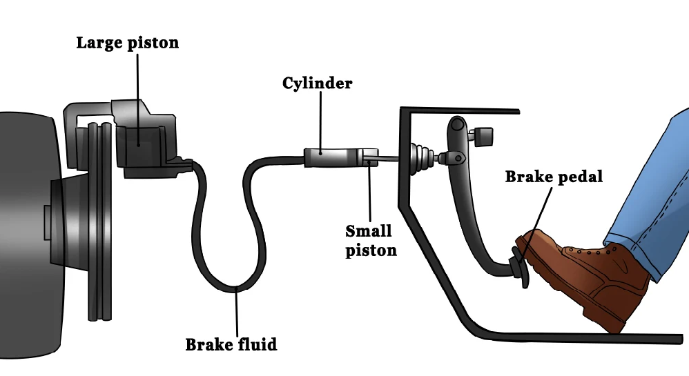
- As an example, friction is present in the braking system as when the driver pushes the brake pedal and shifts the braking fluid, which sends hydraulic pressure to the brake caliper, which cause the brake pads to contact the brake rotor, thereby causing friction, which then slows down the rotor and wheels, while also releasing some of the transferring kinetic energy as heat to the atmosphere.
Two Force Members
- A two force member in our case would be a tube member with forces only acting in two locations, with the forces being equal opposite and colinear.

...
- This is mainly useful when analyzing the loading of a part (say in a simulation setting) where you can pick out two force members of a structure, which simplifies the force layout of the structure and limits the amount of unknowns

...
Materials
Start here → Materials Lecture.pdf
Every material is made up of a crystal structure (crystal defects, a unique organization of atoms, etc.) which leads to materials with unique/different properties (i.e. this is how you get alloys, a mixture of chemical elements with at least one metal).
- You can look more into this on your own, but essentially, we pick a tube material based on its makeup and its properties (weight, density, yield strength, Young’s modulus, etc.)
- Material selection is a lot more in depth with Ergo as compared to Frame, as you the specifications for each part may vary. While the entire frame needs to be one rigid piece, welded together and uniform, a single material will be used like 6361 aluminum or 4130 chromoly steel. However, with Ergo, you may need a light weight brake and accelerator pedals that are subject to a lighter load, but require a more rigid, easily weldable metal for the belly pan, that must hold high amounts of weight and therefore be exposed to high stress.


This is a stress-strain curve, one of the most fundamental parts of Solids. The graph has stress on the y-axis, strain on the x-axis
What you need to know is:
- The elastic region is where the material can have stress applied (elastic deformation) and the process is reversible (the material can go back to its original length)
- The elastic line on the graph is linear because the stiffness of material in this region is like a spring (most materials mimic the processes of a spring when it comes to deformation)
- This is also the same place where Young's Modulus comes into play.
- Young's Modulus is simply just a number that represents the "stiffness" of a material, representing the ratio of stress over strain. This is unique to each and every material.
- Most importantly, higher young's modulus means a more brittle material (less strain/yielding, can withstand more stress, but more prone to fracturing)
- The plastic region is where the material has stress applied (plastic deformation) and the stress overcomes the energy required to rupture bonds, which is an irreversible process
- Two important things: Yield Strength and Ultimate Strength
- Yield strength is the maximum stress a material can absorb before plastically deforming
- Ultimate strength is the maximum stress a material can absorb before fracturing (breaking)
- I’ll talk about this later on in the guide when we get to welding, but essentially, just know that we mainly design things around the yield/ultimate strength.

Pictured above, is a stress-strain graph showcasing some common materials. From left to right, we go from harder, higher "strength" materials, that lightly yield, to softer materials, lower "strength" materials, that yield more.
- Strength in this case just means a materials ability to take resist breaking when a stress is applied. A stronger material can take more stress before permanently breaking.
Another key point of materials that is more in play with Ergo as opposed to Frame is Resiliency as opposed to purely using Toughness.
- Resiliency is the ability of a material to absorb energy again and again without having some sort of permanent deformation. Think of a material like rubber, that has a fairly low work of fracture (meaning it can be easily fractured with a small-ish amount of energy) but if that level of energy is not reached, the rubber can yield again and again without deforming permanently.
- Toughness refers to sort of the same thing, but instead of focusing on permanent deformation (which can occur before and without any sort of fracture), Toughness focuses on the ability of a material to absorb energy without fracturing. This is more so a higher number with heavier metals, where a resiliency is better in softer materials that can easily rebound.
- In reference to Ergo, like previously mention, different parts require different materials for their intended situations. Specifically, sometimes you will need a material with the ability to not yield much and be able to take lots of energy and stress before yielding (like a brake pedal, as you'd never want your brake pedal to take the force of your foot by bending instead of activating your brakes). On the same hand, sometimes you'll want a softer material that can take a load, yield, but still not fracture and will go back to its original position afterward (think of anything with rubber or foam, like pieces of a seat or steering wheel)
Lastly, the Factor of Safety, at least in our case is measured with the yield strength of the material, as well as the max von Mises equivalent stress from the given simulation/reaction (the equation is Max eq stress/yield strength).
- This indicates when a part can fail
- FOS of 1 means the current simulation/reaction will begin to fail at 1 times the max equivalent stress, 2 means the structure begins to fail at 2 times the max equivalent stress, etc.
- FOS of 1 is the absolute bare minimum a structure should have before it is deemed manufacturable, but some parts of the frame must have a 1.1 minimum, due to high safety goals/concerns (although you should always shoot for something >1.6 FOS)
...
Solids
Start Here → Solids Lecture.pdf

There are 4 main types of stresses each tube will encounter. Those include:
- Normal Stress: Stress that acts perpendicular to the cross-section of interest (compression, tension, or rather axial force)]

- Shear Stress: Stress that acts tangential (parallel) to the cross-section of interest (like a cutting force)
- A common application of this is bolt shearing. This is where pre-tensioning, torqueing, and bolt calculations come in to play (tbd, I am learning about these currently)
- Torsional Stress: A shear stress that is caused by a moment about the longitudinal axis of the tube (think of a twisting force)
- Bending Stress: (THIS IS THE BAD ONE): Stress caused by a moment that has tension and compressive stress at each end (think of the cantilever beam problem below
- Also, bending stress is related to moment of inertia
- Simple Bending or Pure Bending A beam or a part of it is said to be in a state of pure bending when it bends under the action of uniform/constant bending moment, without any shear force. Alternatively, a portion of a beam is said to be in a state of simple bending or pure bending when the shear force over that portion is zero. In that case, there is no chance of shear stress in the beam. However, the stress that will propagate in the beam as a result will be known as normal stress. Non-uniform bending occurs when shear forces are introduced.


- Above is the formula for bending stress on this cantilever beam. Here, we have bending stress on the left side, with the calculated bending moment times the vertical distance from the neutral axis, all over the moment of inertia from the neutral axis
- What you really need to take from this is not necessarily all the algebra behind bending stress, but rather the things that affect the value itself, which in this case is bending moment, moment of inertia, and vertical distance.
...
Fluids/Thermodynamics
Specific to Ergonomics, you'll also utilize some Fluid Mechanics and Thermodynamics knowledge as it pertains to the braking system.
At its core, a braking system (or at least what Ergo deals with) is an assembly of brake lines, the brake pedal/E-brake, proportioning valve, and braking fluid, that converts the force of your foot on the pedal, into mechanical energy via a piston cylinder and fluid (this is the Thermodynamics aspect), and thereby into braking force on the brake rotors and by extension the wheels of the car.
A big point as it pertains to the braking system is the difference of compressible vs. non-compressible substances/fluids. In the braking system, we are working with brake fluid, which like water, is an incompressible fluid, meaning that when a pressure is applied, the fluid will move and transfer that pressure as opposed to taking it and becoming compressed.
- However, when setting up a braking system, it's important to bleed your brakes, which just means purging the system of air bubbles. When you install brakes and therefore brake fluid, bubbles are present in the lines before bleeding. Because air IS compressible as opposed to your brake fluid, the air will compress and take energy and pressure away from the brake fluid as it's trying to move and activate your brakes. This is what causes a brake to become squishy and unresponsive, as when air bubbles are present you are basically just compressing and decompressing the air with minimal brake fluid movement.
- On the same type of note, using Thermodynamics, we know that when this pressure is applied, some of that energy flowing through the fluid will transfer to heat energy, which lead to brake fluid boiling. This is more so a concern of the driver (as excessive/improper braking is the cause of brake boiling), but this also plays into brake fluid selection. At its core, just like any water, is it is boiled, vapor is released, which contains air bubbles. As previously mentioned, if your brake fluid is boiling, and therefore, you create air bubbles, well I think you know where I am going with this...
More on the fluids side, there's some key principles that are helpful in setting up an optimized braking system

Firstly, Bernoulli's Principle refers to how fluid pressure and velocity are affected by the diameter of the tubing/line of a fluid (in our case the brake line)
- Simply put, if we assume the flow rate is the same across the entire tube/line, when the tube has a larger cross-sectional area/diameter, there's more volume in the tube, meaning the fluid travels slower and with higher pressure to achieve the same flow rate
- On the opposite side of the spectrum, when the tube or line has a smaller cross-sectional area/diameter, there's less volume, meaning the fluid must work harder and travel with more velocity to achieve the same flow rate, albeit with less pressure
- This is applicable when thinking about the sizing of your lines, especially as your braking ability is determined by the ability to move pressure from the brake pedal, through the fluid and to the actual brakes
Additionally, we have the different types of flow, laminar and turbulent flow, at play as well.
- Laminar Flow refers to a flow with little turbulence, creating a smooth, consistent stream
- Turbulent Flow is the opposite, referring to a more chaotic, inconsistent flow, that occurs due to turbulence
- Turbulence is just a term for irregular motion, like swirling and unpredictable changes in motion
- Point here being, you want to achieve laminar or close to laminar flow when possible as it's predictable and consistent. You want predictable and consistent braking ability right?
Lastly, piggybacking off of the types of flow, consider the pathing of your tubing. Consistent and smooth fluid streams are naturally better suited to straight, consistent paths, but inevitably you might need to change the directions and pathing of your lines.

- When creating direction changes in these lines consider the resultant drag caused by the abrupt change in the fluid's path as well as the turbulence it can create, which further affects the pressure and velocity values of the flowing fluid
- The red pockets on the corners symbolize points of flow separation, which just means that the smooth stream is broken up into sections, causing turbulent flow and pressure losses.
- All in all this just means that you should for as straight and consistent as a path as possible, and if you have to, utilize more gradual, smoother turns, as more abrupt and constant turning hurts fluid flow, leads to excess drag, as well as lots of pressure drops and turbulence
...
Topology Optimization
Useful Tidbits
...
Ergo Idea dump  :
:
...