Overview
The goal of this project is to design a mechanism to emulate the motion of casting a fishing rod. The primary focus of this project is not to perform a long cast or reel in large objects, but rather to achieve a smooth and realistic casting motion. Our first objective was to define the line of motion for our mechanism. We used MotionGen software to visualize and prototype possible configurations of our linkage.
While our initial linkage model successfully recreated the path traced by the tip of a fishing pole during casting, we felt that the repositioning motion after the initial forward swing was awkward and unrealistic. A true cast and reel would be modeled as a fluid, continuous motion. Our solution was to redesign the mechanism with links that achieve a full range of motion, particularly the output link that traces the path of the pole tip.

Initial Mechanism Concept
During our research, we discovered that a geared five-bar linkage is capable of achieving the figure-eight motion shown below when the gears rotate in opposite directions. This motion provides the same general shape as our original mechanism, but the output link travels on a continuous path that more closely resembles our desired trajectory.
Geared Five-Bar Mechanism Path of Motion
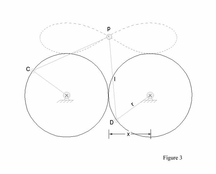
Further experimentation with gear orientation, gear diameter, and link lengths resulted in different versions of the figure-eight motion. After several iterations, we decided that the linkage depicted below best represented the natural motion of casting. For this configuration, the gears have the same diameter (gear ratio of one) and have equal but opposite angular velocities. An additional benefit of this five-bar linkage is that it requires only one force input, allowing the mechanism to be powered by one input motor.

Current Linkage Configuration
While one of the goals of this project is to incorporate intermittent motion with a Geneva mechanism to represent the waiting period between casts, we decided to focus on the main gear and link assembly for the first prototype. We felt that prioritizing the five-bar mechanism and achieving smooth, continuous motion was the most important accomplishment at this stage of the design process. Using the link dimensions from our MotionGen drawing, we created a SolidWorks assembly to model the 3-dimensional mechanism. Satisfied with this model, we laser-cut and assembled the scaled-down version of our linkage shown below.

SolidWorks Assembly

Scaled-Down Physical Prototype
The motion of our current prototype is much rougher than what we hope to see in our final product. In our next iterations, we will attempt to make the motion smoother by incorporating ball bearings and working with different materials. We also plan to adjust the dimensions of our gears to reduce friction and optimize force transmission.
Kinematic Analysis

Linkage Path of Motion

Animation of Five-Bar Mechanism

Angular Velocity of Output Link

Linear Velocity of Output Link

Acceleration of Output Link
Iteration Documentation
Sketches, animations, and kinematic analyses of previous design iterations.


Bill of Materials
Below is a tentative list of materials that will be used as we move toward the final prototype.
- 1/4 in Acrylic Plates x2
- Ball Bearings x5
- 12in x 6mm rod x1
- M3 hex nuts x12
- M3x10 socket head screws x2
- M3x8 socket head screws x4
- M3x6 socket head screws x4
- M3x4 socket head screws x2