Design and Analysis (07)
Ideal Motion/Force Profile:
The ideal motion profile for this problem statement would have the following properties:
- The end effector approaches the bar from above in order to hook itself on
- It then moves backward relative to the body, in order to pull the body forward
- It moves up and forwards to release the bar from its hook
- It returns to its initial position along a lower path to avoid colliding with other bars
The only requirement for the force profile is that the output forces while on the bar are sufficient to move the body.
Mechanism Selection
Two mechanisms have been considered to achieve the desired motion profile:
- A modified version of the 6-bar walking mechanism called the "Klann Linkage"
- A 5-bar "pantograph" linkage with two driven links, in which the two driven links are geared to one another
Our team constructed rudimentary physical prototypes of each linkage system alongside mathematical analysis and simulation to determine which would work best for our purposes.
Ultimately, the Klann Linkage was chosen over the pantograph for reasons which will be discussed.
Mobility Calculations:
Klann Mechanism
Gruebler's Equation: 6 links, 7 full joints. DOF = 3 * (6 - 1) - 2 * 7 = 15 - 14 = 1
Grashof: Links 0, 1, 2, and 3 form a 4-bar linkage. Link 1, the input link for the mechanism, satisfies the Grashof condition (class 1).
Pantograph-like Mechanism
Gruebler's Equation: 5 links, 5 full joints, 1 half joint. DOF = 3 * (5 - 1) - 2 * 5 -1= 12-10-1= = 1
The Mechanism has 1 DOF and has less parts compared to the
Kinematic Analysis:
Force Analysis:
We chose to analyze the forces for the Klann Linkage when it is attached to the bar because this is the only time when the linkage experiences significant forces at the end effector.
Interesting Mechanism Features:
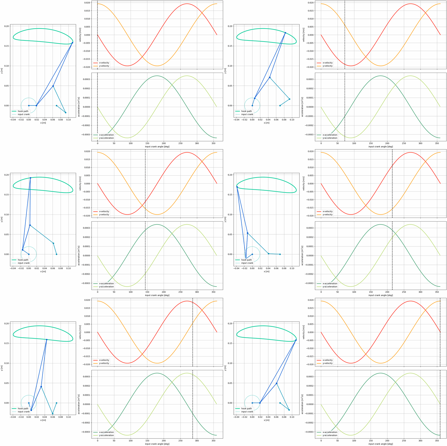
The individual Klann Linkage includes an important feature which allows the robot to unhook itself from the bar while simultaneously hooking on to the next bar. This small lifting action is visible in the Kinematic path animation. However, this action must coincide with another arm's hooking action, so as to transfer the weight from one arm to the next. The final requirement of the motion profile complicates this process. This requirement states that "the end effector returns to its initial position along a lower path to avoid colliding with other bars." This "lower" path is bound to be longer than the upper path, thus the end effector takes longer to return to its forward position than the next bar takes to reach it's rear position.
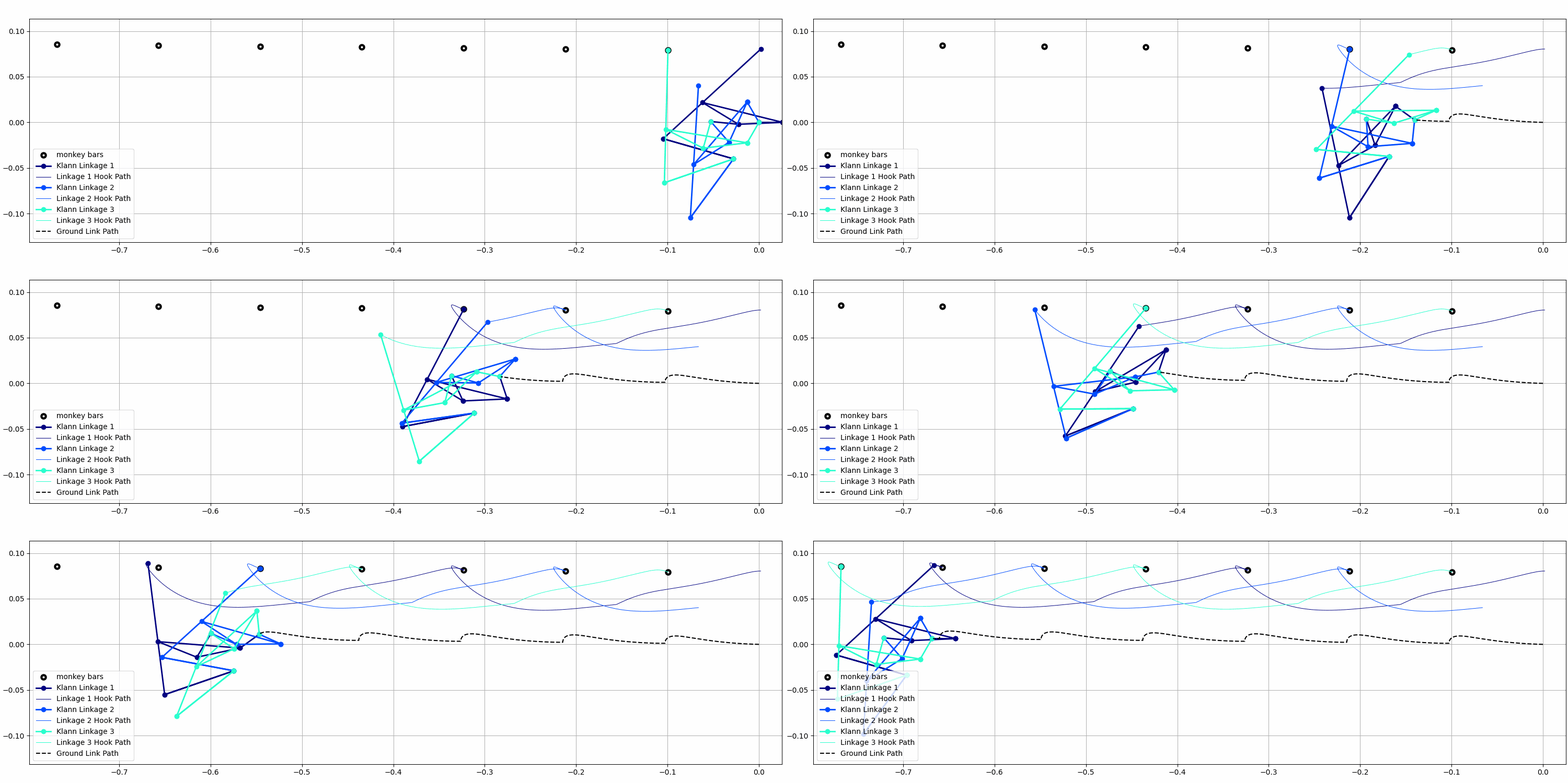
In order to solve this timing issue, we've used a 3-phase system, using three Klann Linkages. Each linkage spend 1/3 of its cycle on the bar, moving the body of the robot forward, then 2/3 of its time returning to its forward position in order to grab hold of the next bar. This system is shown in the animation below. Key features to note are that:
- the end effectors approach the bars from underneath (in front of the bar), raise above the height of the bar, then come down and back to hook onto the bar
- there is a slight upward lift of the end effector as it unhooks from the bar
- during the return motion of each end effector (while it is not hooked to a bar), its path never crosses over any of the subsequent monkey bars
Animation:
3-Phase Klann Linkage Simulation (axes in meters) source code
In the above animation, three distinct Klann Linkages are joined together to form a 3-phase system in which one of each of the three end effectors is always in contact with one monkey-bar. Each color represents a separate Klann Linkage. The three arms are linked together at the "ground" of each linkage, the path of which is traced using the black dotted line. The path of the end effector of each arm is traced in the color of that arm. The black circles represent the monkey bars, such that as each arm makes contact with a black circle, it is "hooked" to it. (This shows a single 3-phase system, a physical robot would require at least two 3-phase systems to maintain it's angle relative to ground.)
2-Phase Pantograph Simulation (axes in meters)
The pantograph would operate as a 2-phase system, however the motion profile of the unhooking action does not contain the lifting motion that is present with the Klann Linkage system. This is the primary reason the pantograph design was discarded. The lack of a distinct unhooking motion means that the hook itself would need additional complexity to handle that task.
Kinematic analysis and simulation source code available on github


Welcome to the University Wiki Service! Please use your IID (yourEID@eid.utexas.edu) when prompted for your email address during login or click here to enter your EID. If you are experiencing any issues loading content on pages, please try these steps to clear your browser cache.