This robotic gripper design employed many of the concepts learned in class and from the Design of Machinery textbook. When thinking about the end result of closing and opening motion necessary for a gripping
...
operation, I knew that it needed to be two
...
4-bar mechanisms that mirrored each other, similar to the below figure.
...
Figure 1: Four-bar linkage used for closing motion of robotic gripper
...
The lengths for the link between points 1 and 3, 1 and 5, 3 and 6, & 5 and 6 were taken from the step file, but
...
their relative lengths do follow this template.
Figure 1: Four-bar linkage used for closing motion of robotic gripper
With that settled, the next decision to make was with regards to how to get that rotational input motion into the points 1 and 2 above.
...
An easy solution would be to add motors to those points, but this would be not be in line with the objectives of the project: achieving optimal maneuverability with the fewest possible actuators. Also if the motors started at different points or their timing got off from each other, that could introduce kinks into the system and shear the fragile PLA parts. One potential option that was explored was to use a worm gear to drive two gears on either side of it, which would then rotate link 2. A simulation of the design in action is shown below.
Widget Connector url https://www.youtube.com/watch?v=HMQ4u9UlPSQ
Before considering the kinematic design of the cutting arm linkage mechanism, we had to learn how professional chefs cut vegetables. When using a large chef knife for relatively small vegetables, the knife blade is typically left in contact with the cutting surface. This blog was helpful in deciding a knife path (and is the source of figure 1).
Initially a fourbar mechanism was considered to drive more complex motion. However, this would leave the knife end unsupported, which could result in poor cuts or possible safety issues. To better constrain the system, a slider crank was chosen. This is also a good choice because the knife needs to stay in constant contact with the cutting surface, so the sliding axis will be parallel to the cutting board. Lastly, the knife itself can be used as the slider crank output coupler, further simplifying the design.
In order to choose the input coupler length, the effective cutting length of the knife was found. This is the length of the knife available for cutting, which is equal to the overall blade length minus the end clamp length, maximum vegetable diameter (chosen to be 1.5"), and tolerance for minor misalignment. This came out to about 5", which was set equal to the diameter of the input coupler's circlular path. This leads to the input coupler having a length of 2.5".
For safety reasons and practicality, machining modifications to the knife were as limited as possible. The handle connection was initially intended to be a drill and tap into the dowel pin; however, the knife was cheap and the "dowel pins" ended up being thin aesthetic disks. Because of this, a portion of the rubber handle was removed and a custom part was made for the connection. At the knife end, a simple clamp was made to safely hold the blade. This allowed for small adjustments in case the knife CAD wasn't fully accurate. After these attachments were modeled, the knife linkage length from the handle pin to the clamp shaft was found to be 11.75".
The last step in completing knife kinematics was finding the position of the sliding axis relative to the driven axis. Since the knife has complex geometry, it is difficult to do a standard simulation to choose the best linkage ratios. Given this, it was important to create a precise 3D model of the knife. To do this, the knife was photographed next to a ruler. Using the ruler as a scale, the outline of the knife was traced in SolidWorks using splines, and extruded to measured specifications. After this step, the vertical distance between the driven axis and the slider rail was found by incrementally adjusting the value in CAD, eventually approaching a value of 2.275". A small notch was machining in the cutting board to account for slight errors, assist with alignment, and ensure the vegetable was fully cut.
Once the vertical distance was found, the slider crank was examined at its toggle positions to find the rail length. Figure 2 shows the fully defined mechanism. At this point, every dimension was fully defined, so kinematic analysis could take place. To do this step, a tool called PMKS (Planar Mechanism Kinematic Simulator) was used. This software calculates position, velocity, and acceleration of linkages in most standard mechanisms. (Unfortunately, it only runs in Internet Explorer.) The slider crank used for this project can be found here, as seen in figure 3.
...
Figure 2: Worm/Spur Gear Application for Closing Gripper Tips
A worm gear is a gear consisting of a shaft with a spiral thread that engages with and drives a toothed wheel. Further descriptions of worm gears can be found here: https://www.machinerylubrication.com/Read/1080/worm-gears. A picture of an industrial slew drive, which uses a spur gear to achieve rotation is shown in the figure below. Spur gear drives are used for high rotational speeds and quick acceleration at nominal-to-low torque loads. Worm gear drives, on the other hand, are slower in speed but can magnify an input torque at much higher ratios than a typical spur gear system.
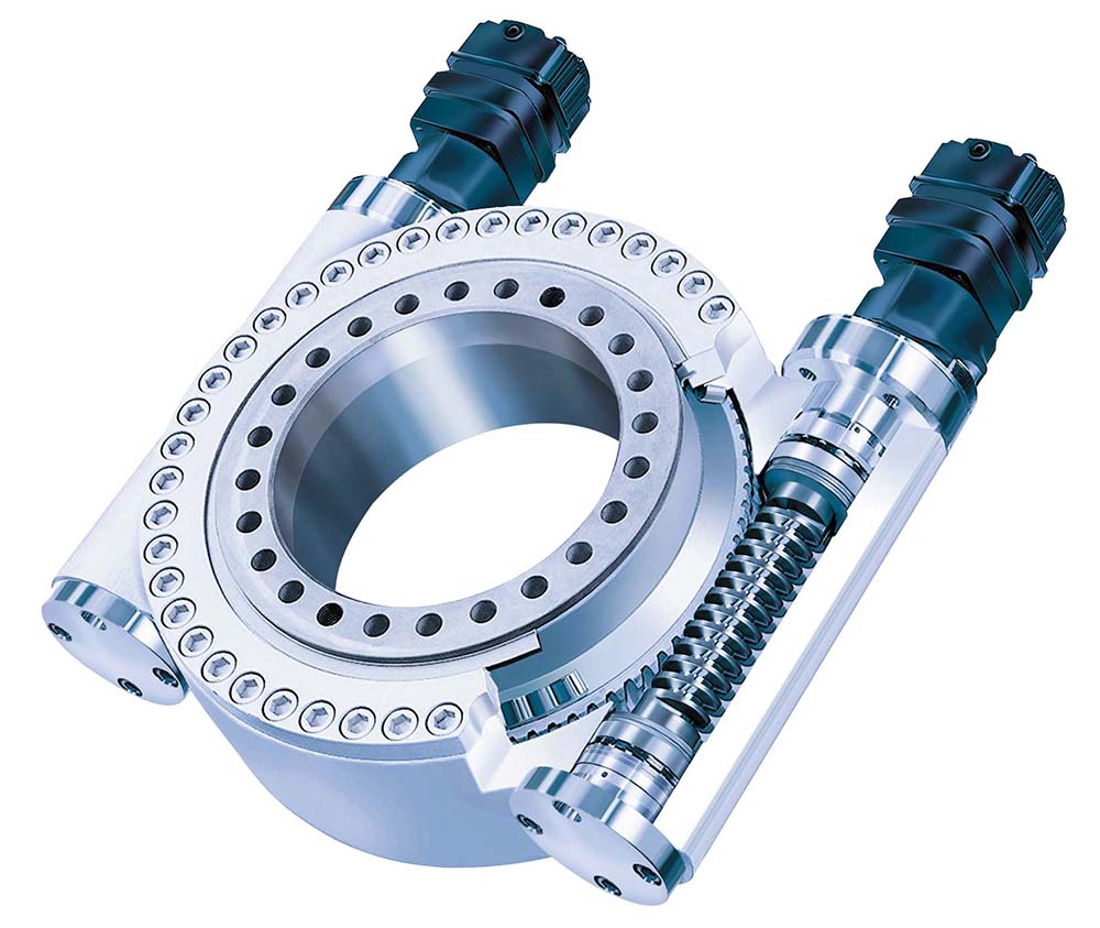
Figure 3: Slew drive, utilizing a spur gear
A simple off-the-shelf slew drive can be purchased here for any future teams looking to integrate in such a mechanism into their designs, https://agricultural-gearbox.en.made-in-china.com/product/tFnQgYATozVG/China-Small-Slewing-Drive-Endless-Rack-and-Pinion-Screw-Motor-Shaft-Wheel-Motor-Plastic-Helical-Bevel-Spur-Worm-Gear-Mechanism-Set-Arrangement.html. While the slew drive was an enticing option, it would have taken too long to machine our own spur gear or purchase it from across the pond. As such a simpler option was explored, albeit while sacrificing performance.
The original inspiration simulation had an additional 5-bar mechanism (Mechanism A), with its final link being connected to the 2nd link of the final 4-bar mechanism (Mechanism B). An illustration is shown below for context. This design only relied on fixing a threaded rod (link 2) to the ground body of the robotic gripper and allowing link 3 of the Mechanism A to move back and forth along the rod. This is made possible by introducing a threaded feature into the center region of link 3. All that is required is to attach the threaded rod link to an rotational motor input. The threaded rod could be replaced by introducing a linear actuator, but this is is by far the simplest option with keeping the scope of the project in mind. This actuation concept with the linear threaded rod mimics the slider-crank mechanism that was discussed and analyzed at length during class. This is because the slider is the input (link 3 of Mechanism A) and the crank is the output (rotary links connected to the final gripper link of Mechanism B).

Figure 4: Sketch of Robotic Gripper and its 2 Internal Planar Mechanisms
Once again, the lengths of links involved with this 5-bar mechanism were taken from the original .stp file, but many alterations had to be made in order to avoid any interference issues that were not considered in the original design. The final design, along with the motor generating the input rotation (and thus the resulting linear motion of link 3) is also shown in the CAD.

Figure 5: CAD Assembly of both mechanisms and input motor
When testing the design for functionality by moving the links around in Solidworks, I saw some interesting conditions that revealed to me that there were multiple solutions to the angles of the other links, given the same linear distance input of link 2 of Mechanism A. Some examples of the multiple solutions are shown below. It was reasoned that many of these undesirable cases would never be seen on our robot based on how we initially connected our links (with our particular Grashof condition) and due to the mirrored gripper tips touching each other, preventing motion before one of the strange configurations would be allowed to develop.


