2. Mechanism Design
- Connor Crawford
This robotic gripper design employed many of the concepts learned in class and from the Design of Machinery textbook. When thinking about the end result of closing and opening motion necessary for a gripping operation, I knew that it needed to be two 4-bar mechanisms that mirrored each other, similar to the below figure. The lengths for the link between points 1 and 3, 1 and 5, 3 and 6, & 5 and 6 were taken from the step file, but their relative lengths do follow this template.
Figure 1: Four-bar linkage used for closing motion of robotic gripper
With that settled, the next decision to make was with regards to how to get that rotational input motion into the points 1 and 2 above. An easy solution would be to add motors to those points, but this would be not be in line with the objectives of the project: achieving optimal maneuverability with the fewest possible actuators. Also if the motors started at different points or their timing got off from each other, that could introduce kinks into the system and shear the fragile PLA parts. One potential option that was explored was to use a worm gear to drive two gears on either side of it, which would then rotate link 2. A simulation of the design in action is shown below.
Figure 2: Worm/Spur Gear Application for Closing Gripper Tips
A worm gear is a gear consisting of a shaft with a spiral thread that engages with and drives a toothed wheel. Further descriptions of worm gears can be found here: https://www.machinerylubrication.com/Read/1080/worm-gears. A picture of an industrial slew drive, which uses a spur gear to achieve rotation is shown in the figure below. Spur gear drives are used for high rotational speeds and quick acceleration at nominal-to-low torque loads. Worm gear drives, on the other hand, are slower in speed but can magnify an input torque at much higher ratios than a typical spur gear system.
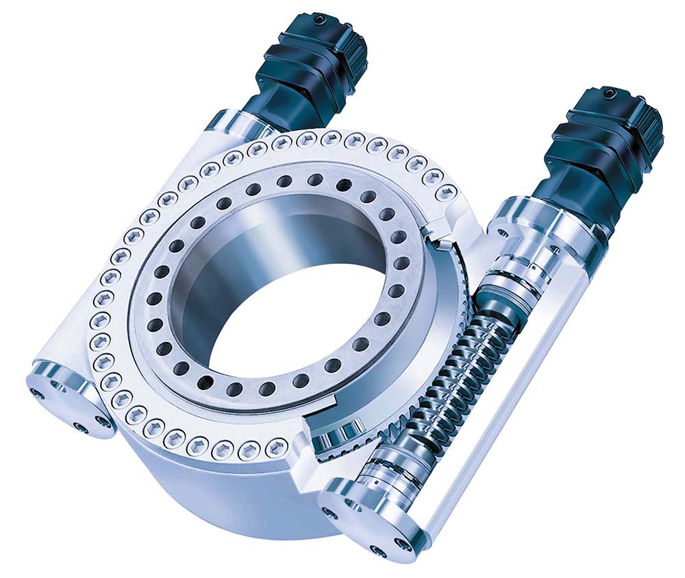
Figure 3: Slew drive, utilizing a spur gear
A simple off-the-shelf slew drive can be purchased here for any future teams looking to integrate in such a mechanism into their designs, https://agricultural-gearbox.en.made-in-china.com/product/tFnQgYATozVG/China-Small-Slewing-Drive-Endless-Rack-and-Pinion-Screw-Motor-Shaft-Wheel-Motor-Plastic-Helical-Bevel-Spur-Worm-Gear-Mechanism-Set-Arrangement.html. While the slew drive was an enticing option, it would have taken too long to machine our own spur gear or purchase it from across the pond. As such a simpler option was explored, albeit while sacrificing performance.
The original inspiration simulation had an additional 5-bar mechanism (Mechanism A), with its final link being connected to the 2nd link of the final 4-bar mechanism (Mechanism B). An illustration is shown below for context. This design only relied on fixing a threaded rod (link 2) to the ground body of the robotic gripper and allowing link 3 of the Mechanism A to move back and forth along the rod. This is made possible by introducing a threaded feature into the center region of link 3. All that is required is to attach the threaded rod link to an rotational motor input. The threaded rod could be replaced by introducing a linear actuator, but this is is by far the simplest option with keeping the scope of the project in mind. This actuation concept with the linear threaded rod mimics the slider-crank mechanism that was discussed and analyzed at length during class. This is because the slider is the input (link 3 of Mechanism A) and the crank is the output (rotary links connected to the final gripper link of Mechanism B).

Figure 4: Sketch of Robotic Gripper and its 2 Internal Planar Mechanisms
Once again, the lengths of links involved with this 5-bar mechanism were taken from the original .stp file, but many alterations had to be made in order to avoid any interference issues that were not considered in the original design. The final design, along with the motor generating the input rotation (and thus the resulting linear motion of link 3) is also shown in the CAD.

Figure 5: CAD Assembly of both mechanisms and input motor
When testing the design for functionality by moving the links around in Solidworks, I saw some interesting conditions that revealed to me that there were multiple solutions to the angles of the other links, given the same linear distance input of link 2 of Mechanism A. Some examples of the multiple solutions are shown below. It was reasoned that many of these undesirable cases would never be seen on our robot based on how we initially connected our links (with our particular Grashof condition) and due to the mirrored gripper tips touching each other, preventing motion before one of the strange configurations would be allowed to develop.


Welcome to the University Wiki Service! Please use your IID (yourEID@eid.utexas.edu) when prompted for your email address during login or click here to enter your EID. If you are experiencing any issues loading content on pages, please try these steps to clear your browser cache.