...
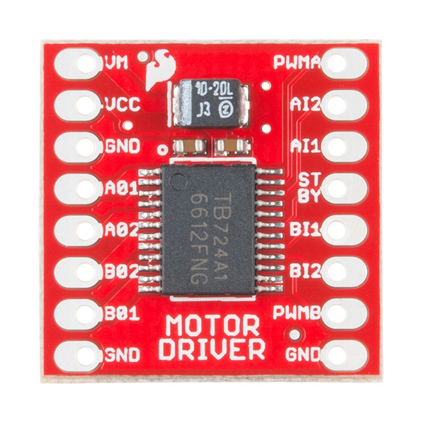
The electrical assembly was also not overly complex. We used only one integrated circuit board, a Sparkfun motor driver. Between the 12 volt power supply, 5 volt supply pin, ground, and various logic pins we were able to connect the two A channel outputs of the motor driver to the input terminals of our continuous DC motor.


Software
We used the Arduino IDE to code our project, as the scope of our code was extremely limited. Besides initializing certain logic pins, we used two different functions for our project. One for setting PWM output based on duty cycle, as well as setting GPIO output to being either logic LOW or logic HIGH.
...