Electrical
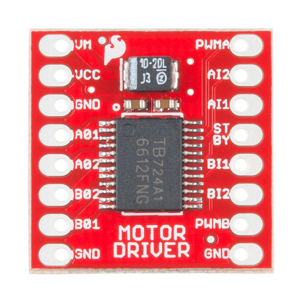
The electrical assembly was also not overly complex. We used only one integrated circuit board, a Sparkfun motor driver. Between the 12 volt power supply, 5 volt supply pin, ground, and various logic pins we were able to connect the two A channel outputs of the motor driver to the input terminals of our continuous DC motor.


Software
We used the Arduino IDE to code our project, as the scope of our code was extremely limited. Besides initializing certain logic pins, we used two different functions for our project. One for setting PWM output based on duty cycle, as well as setting GPIO output to being either logic LOW or logic HIGH.
// Defining our motor driver logic inputs pins as PIN2 and PIN4
#define Input1 2
#define Input2 4

// Defining our motor driver PWM input pin as PIN3
#define PWM 3

// Defining a direction constant
#define CCW 0
#define CW 1

// Setting up the duty cycle of our PWM, ranges from 0 to 255
int DutyCycle = 80;

// Setting up the variable that controls motor direction
int Direction = CW;

void setup() {
// put your setup code here, to run once:

// Setting digital GPIO pins as output
pinMode(Input1,OUTPUT);
pinMode(Input2,OUTPUT);

// Setting digital PWM pins as output
pinMode(PWM,OUTPUT);
}

void loop() {
// put your main code here, to run repeatedly:

// Setting the direction of the rotation
if (Direction == CCW) {
digitalWrite(Input1,HIGH);
digitalWrite(Input2,LOW);
} else if (Direction == CW){
digitalWrite(Input1,LOW);
digitalWrite(Input2,HIGH);
} else {
digitalWrite(Input1,LOW);
digitalWrite(Input2,LOW);
}

// Setting up the rotation speed
analogWrite(PWM,DutyCycle);


// Simple delay
delay(1000);

}
Welcome to the University Wiki Service! Please use your IID (yourEID@eid.utexas.edu) when prompted for your email address during login or click here to enter your EID. If you are experiencing any issues loading content on pages, please try these steps to clear your browser cache.